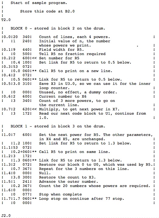
Firstly, the format of the code above:
This was typed into a plain text editor, then processed to make a .TAP file for Chris Burton's simulator. The intention is to replicate the way we used to write programs for the Pegasus (see this example). The left hand column is the computing store address in which each instruction is executed, the right hand column is commentary, and the middle column specifies the instructions read onto the drum by Initial Orders. The pre-processor simply discards everything between pairs of shrieks.
If you'd like to run this program yourself on the Pegasus, the first step is to get Chris's emulator going, as he shows you in the downloaded materials. Then you can download my pre processor bundle, which includes the above program, and offer the resulting .TAP file to the emulator. To run Lavington's example as given in the book, you need to use the Assembly system, which he mentions in passing without explanation. This is perfectly possible, but demanding. Like all else in Pegasus programming, Assembly is fully covered by George in the manual.
I am myself very keen to help anyone learning to program the Pegasus, and should readily respond to an email describing any difficulty, or pointing out any mistakes I've made.
Next, what this example does:
Using the subroutine R5, the program punches out the square, cube, and fourth power of the natural numbers from 1 to 20. Lavington has nicely reproduced the output, using the font of the original Creed teleprinter. The following is the gist of the output produced when I ran the program printed above (to see it aligned exactly as output, including any spaces omitted by your browser, see this text file):
***
T 53.0 [
B 53.0 [ these lines reflect the loading of subroutines.
T 57.0 [
T 2.0
J 2.0
+1 +1 +1 +1
+2 +4 +8 +16
+3 +9 +27 +81
+4 +16 +64 +256
+5 +25 +125 +625
+6 +36 +216 +1296
+7 +49 +343 +2401
+8 +64 +512 +4096
+9 +81 +729 +6561
+10 +100 +1000 +10000
+11 +121 +1331 +14641
+12 +144 +1728 +20736
+13 +169 +2197 +28561
+14 +196 +2744 +38416
+15 +225 +3375 +50625
+16 +256 +4096 +65536
+17 +289 +4913 +83521
+18 +324 +5832 +104976
+19 +361 +6859 +130321
+20 +400 +8000 +160000
Now, a glossary:
Many operations take place between a computing store location and an accumulator. For example, the instruction <5.3 310> means 'copy the contents of X3 to U5.3'.
There are 8 accumulators, X0 to X7, though X0 is not a real accumulator – it is always a source of zeroes, so that <5.3 010> means 'set U5.3 to zero', and
<0.5 060> means 'jump to U0.5 unconditionally' – while <0.5 160> means 'jump to U0.5 if X1 is zero',
The accumulators come at the beginning of the computing store addresses, so that the instruction <6 300> means 'copy the contents of X6 to X3'.
in a document, denotes a block on the drum. For example B68 denotes block number 68, and B68.4 denotes word 4 in that block.
It turns out that the most convenient way of storing numbers is as a sequence of ones and noughts; for example five is 101, eleven is 1011, and two hundred million is a rather longer string of ones and noughts. The term bit is used to denote one element in such a sequence; it may take the value 1, or the value 0, but no other.
The term byte, much used to specify storage capacity, is (now) a collection of eight bits. A byte can take any value between 0 and 255, and it is no coincidence that two to the power eight is 256.
Pegasus is not spoken of in terms of bytes. We prefer the term word, which denotes a sequence of about forty bits, much discussed throughout the book.
A programmer’s term. When you want to stop execution of a program at a particular point, so that you can see what is happening, you ‘set a breakpoint’ at that point. These days, control passes to a debugging system1. But, in Pegasus times, you changed bit 0 of the word, at that point, from its normal value 1, to the value 0. If and when the point is reached, the whole machine comes to a halt, and the programmer can fiddle about with the switches, to the great frustration of his waiting colleagues.
In Pegasus, all breakpoints may be disabled by operating a physical switch on the control panel.
This is a set of 48 words, each of which may be accessed in much less time than a word on the drum.
These locations are the only ones from which instructions can be executed; furthermore, apart from instructions transferring information to and from the drum, the instruction operands must also be in the computing store.
Information is often transferred in blocks of 8 words, since the drum is organised in 8-word blocks. It is thus conventional to represent a computing store word by block and position. This is purely conventional, with no hardware significance; it is however recognised by Initial Orders when reading instructions, so that U3.1 specifies address 892, and Initial Orders generates this address as part of the instruction <3.1 261> which means 'Jump to 3.1 if X2 is non-zero'. In binary, in the CRT displays, this looks like:
|.||..| .|. ||...| ...
and we notice that the operand specified by the leftmost 7 bits is indeed 89, and that the rightmost 6 bits of this operand are, in octal, <31>, which is what Initial Orders has made of our <3.1>.and then added in the 64, <100> in octal.
Initial Orders...
is the name of the utility program pre-loaded onto the Pegasus Drum. When the spring-loaded Start key is operated, an initial pair of orders is loaded ready to be executed. When the Run key is pressed the Pegasus comes to life and starts reading paper tape.
The paper tape of the sample program above starts with T2.0 , a 'T sequence', and ends with J2.0, a 'J sequence'. These sequences are interpreted by Initial Orders. The T sequence sets the address on the Drum to which information should be transferred. The J sequence tells Initial Orders to stop reading tape, load the given block into U0, and transfer control to the specified word in U0.
Instruction,
or order, denotes an operation performed by the Pegasus, for example 'add the contents of U4.3 to accumulator 2'. We write this as <4.3 201> (see Computing Store). Each instruction occupies 19 bits, so there are two to a word. The remaining bit, of the 39 in a word, is used to indicate a breakpoint.
Paper Tape.
Long before computers, information could be sent along wires. Data was prepared on a teleprinter, and the resulting tape was encoded onto the wires and sent to its destination, where a copy of the tape was produced. This tape was fed into a teleprinter, which rendered the information in print.
Tape was supplied in long rolls, about half an inch wide, with no holes in it. During data preparation, each key pressed caused a row of holes to be punched across the tape, which was then advanced ready for the next row. Each row contained one small hole (the sprocket hole), used to mechanically advance the tape when it was being read, and up to five bigger holes, whose position encoded one of the 32 possible values.
This technology was used to provide the entire input and output capability of the Pegasus. It was used unchanged, except that higher-speed devices were developed for reading the input tape and punching the output tape.
Quite a lot of tape whizzed through the reader, and emerged from the punch. It was collected in big square bins, and spooled up again by hand, using a simple winding machine.
Teleprinter.
This device had a keyboard, a roll of paper about ten inches wide, a tape reader, and a tape punch.
When you pressed a key, the character would appear on the paper, and its encoded form would emerge as a row of holes from the punch. Or, if you had a tape already, you could play it through the reader, and each of its rows would appear as a character on the paper.
The teleprinter played a key rôle in what we should now call the Work Flow. User data would be typed in, the resulting tape would follow an application program tape into the Pegasus, then the output tape would be wound up, printed, and presented to the user.
in a document, denotes a block in the Computing Store. For example U3.1 denotes word 1 in block 3.
Until the 1950s the valve was a key component of all electronic devices, and was made in large numbers. From the computer engineer’s point of view its function can be replicated by one of the millions of transistors in a modern chip. But the valve was many millions of times larger (each one a cylinder of about 100x50mm), and needed electrical power for its heater
A word is in general a collection of a certain number of bits, all together, within the store of a computer. The number of bits, or word length , chosen for a particular computer is one of its vital characteristics. A Pegasus word has 42 bits, of which 39 are visible to a program. The reason for this odd-looking number is ingenious, and discussed throughout the text; one example is the rôle of the leftmost bit: this, if the word is being viewed as a number, indicates its sign – but, if executed as an instruction, the programmer can use it to set a breakpoint.
X,
followed by a digit, denotes one of the eight accumulators.
{
explain link and subroutine}
We assume that a subroutine (named ‘R5’ for no very good reason) is available at block 53. Its parameters are:
Enter at 0.0 to print on a new line, or at 0.2+ to print on the same line.
X6 = the integer to be printed.
X7 = 0, to indicate that just the integer is wanted.
X4 = n, the number of character positions the number
is to occupy. For example, if the number is 1234, and n=8, the output would be 3 spaces followed by ‘+1234’.
All the accumulators are returned as they were at entry.
The only computing store block used is block 0.
1 Usually of great complexity, and very useful, as it is now recognised that software development time is expensive, and it is worth providing the programmer with such tools.
2 The computing store starts at address 64, so Ub.p is at 64+8b+p.